Some simple FPGA stuff
Some articles and links of interest
State Machines
https://hackaday.com/2015/08/13/becoming-a-state-machine-design-mastermind/#more-165086
Verilog IceStorm Series
https://hackaday.com/2015/08/19/learning-verilog-on-a-25-fpga-part-i/
https://hackaday.com/2015/08/20/learning-verilog-for-fpgas-flip-flops/#more-166510
Opencores UART and PWM
http://hackaday.com/2015/12/16/taking-the-pulse-width-modulation-of-an-fpga/
FPGA in C
https://hackaday.com/2015/12/17/xilinx-fpgas-in-c-for-free/#more-182504
Bitonic Sort on FPGA
https://hackaday.com/2016/01/20/a-linear-time-sorting-algorithm-for-fpgas/#more-186026
FPGA motion planning
https://hackaday.com/2016/07/23/manipulators-get-a-1000x-fpga-based-speed-bump/#more-214401
Gravity
https://hackaday.com/2017/01/02/gravity-simulations-with-an-fpga/#more-237384
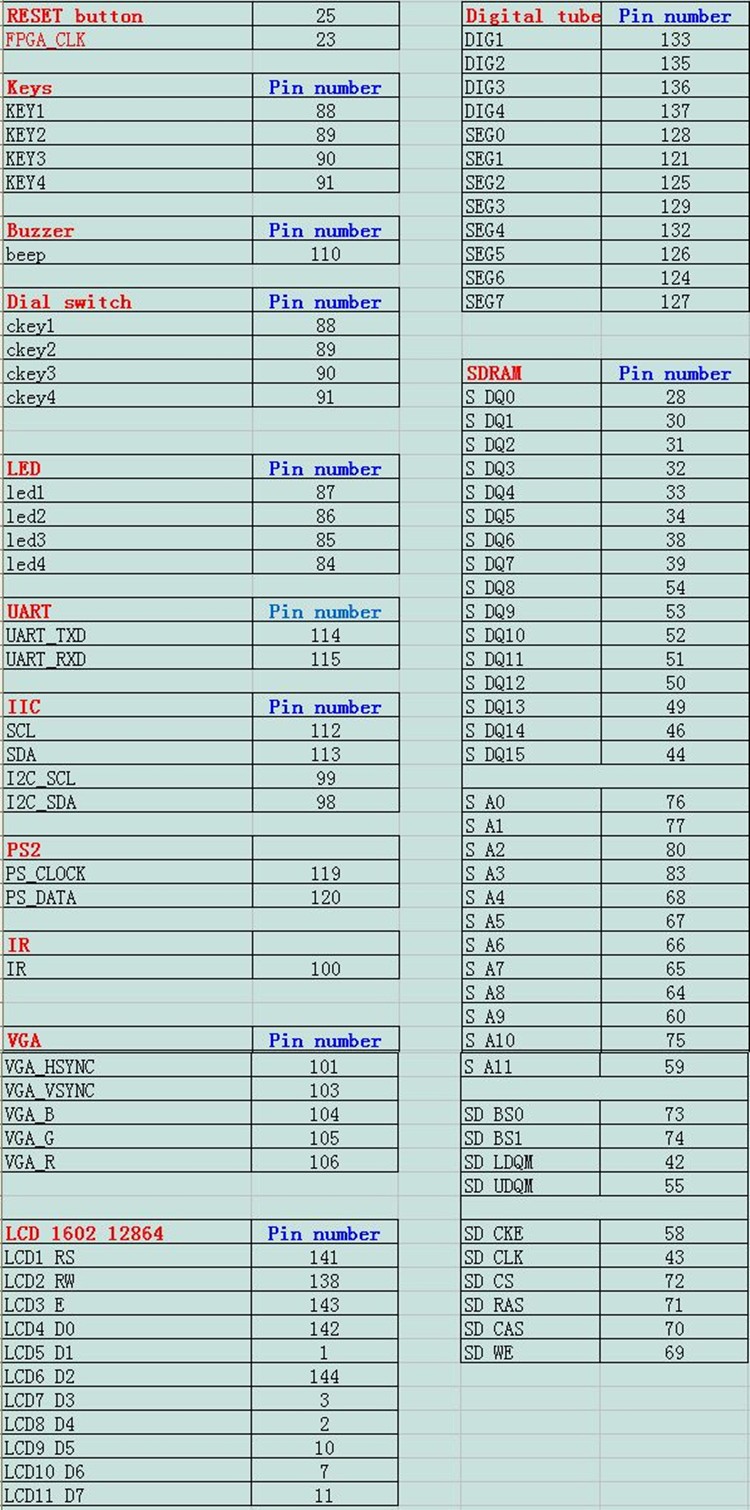
The seller of the Cyclone IV RZ-EasyFPGA A2.1 had the following pinout on the page. I paid about 35$ and it took maybe 3 weeks to get here from china.
It came with a usb blaster programmer. and some usb cables. It can be powered from usb or from a 5 volt supply. I also got a camera.
This is better than the cyclone II chip I had before. More logic units, and I can use the newest version of Quartus II 16.1. I like having some accessories on board
So I have a couple boards now.
Make a new project. Select Cyclone IV E series. EP4CE6E22C8 is the right chip. EP4CE6E22C8N is what the seller says. What does the N mean?
Here is a very simple counter. The clk is 50Mhz clock so I attached bits 25 to the leds in the pin assignment. That should be slow enough for me to see.
make a new verilog file with the same name as the project. This is the top level design file
module blinkcyclone4    (
out     ,  // Output of the counter
clk     ,  // clock Input

);

    output [25:0] out;
//------------Input Ports--------------
     input  clk;
//------------Internal Variables--------
    reg [25:0] out;
//-------------Code Starts Here-------
always @(posedge clk)
begin
  out <= out + 1;
end


endmodule
In the programmer window select the .sof file in the output folder .
Works. Sweet.
Now let’s try getting those LED digits up
http://fpga4fun.com/Opto3.html
Useful reference
The Dig signal needs to be clocked? It probably accepts on a positive edge or something. No. The dig signal is active low. I probably need to have the thing cycle through really fast. There is probably no memory in the led unit
The display is inverted. 0 is on and 1 is off
module led_test    (

input clk     ,  // clock Input
output segA, segB, segC, segD, segE, segF, segG, segDP,
output dig1, dig2, dig3, dig4

);

//wire [3:0] dig;
//assign {dig1,dig2,dig3,dig4} = dig;
assign dig1 = 1'b0;//clk;//1'b1;
assign dig2 = 1'b1;


//reg [25:0]cnt;
//assign dig = cnt[25:22];

//always @(posedge clk) cnt <= cnt+1;

assign {segA, segB, segC, segD, segE, segF, segG, segDP} = 8'b00100101; //8'b11011010;   // light the leds to display '2'
endmodule
This should print a 2 on the first digit.
I went to opencores and got a simple UART core
Put it in the project directory. Add all the files to the porject. Make the loopback example the top level design by right clicking
https://opencores.org/project,simple_uart_for_fpga
Fired up arduino ide serial monitor. Yup. It’s looping back characters. Nice.